geep
New Member

Posts: 26 
|
Post by geep on Jan 7, 2007 19:40:09 GMT -8
I decided to make a set of angle brackets per Steve's plans, which are very good. Working in my spare time I managed to get most of the parts roughed out and one knob made, and the parts for the other knob finished. Never being able to leave things alone, I've made a few "adjustments" in the construction just for fun. Here's the first knob: Materials prepared, maple for turning the shaft, walnut for the thimble and plug. 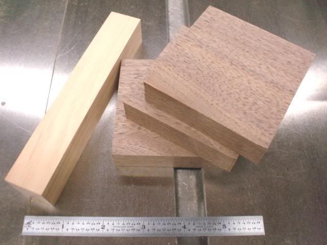 Using an oak spacer behind the walnut blank to prevent the boring bar from cutting the face plate.  Walnut blank mounted to the face plate. 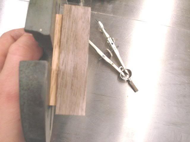 Marking the bore dimension. This will be fine-tuned to the maple barrel. 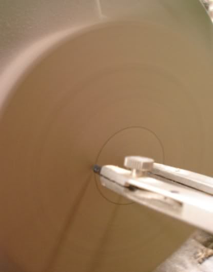 Boring the hole on a pattern maker's lathe. 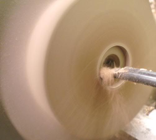 After drilling and chamfering the holes. 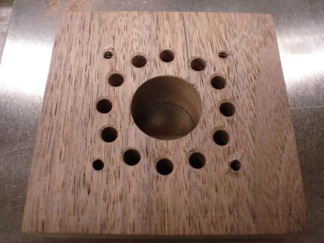 Cutting the knob out on a scroll saw using a spinning jig made from plywood and a scrap knob barrel. 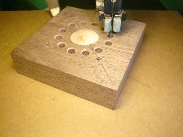 Ready for finish sanding. 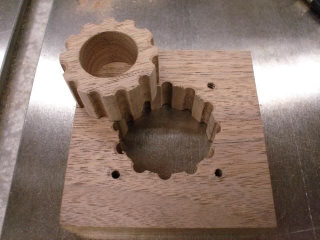 Parts ready to assemble. I used a machine set screw instead of a hex bolt. The hole was bored to rough depth, then I used a mortising machine to make the square recess for the screw. The walnut plug bottoms on the head of the screw. 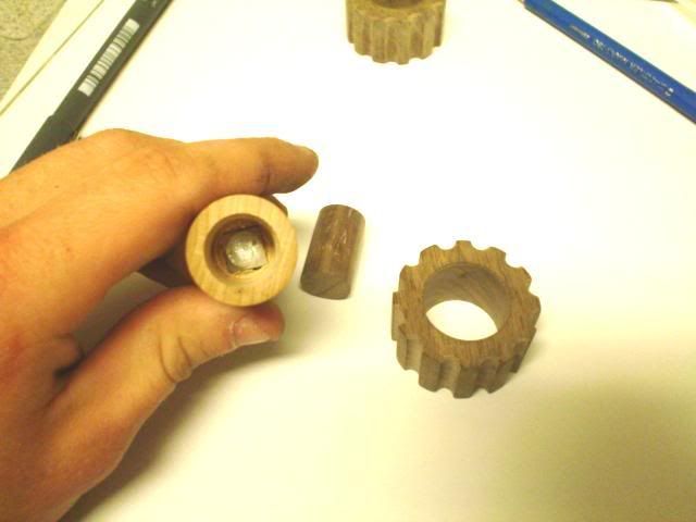 Finished product. 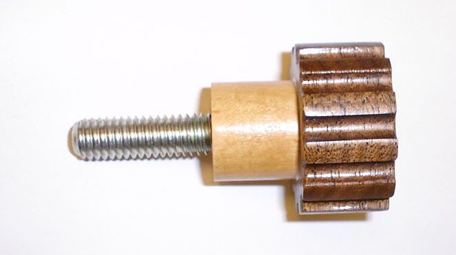 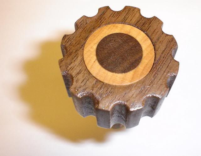 |
|
geep
New Member
Posts: 26
|
Post by geep on Jan 7, 2007 20:02:18 GMT -8
Here's the nearly finished angle bracket: 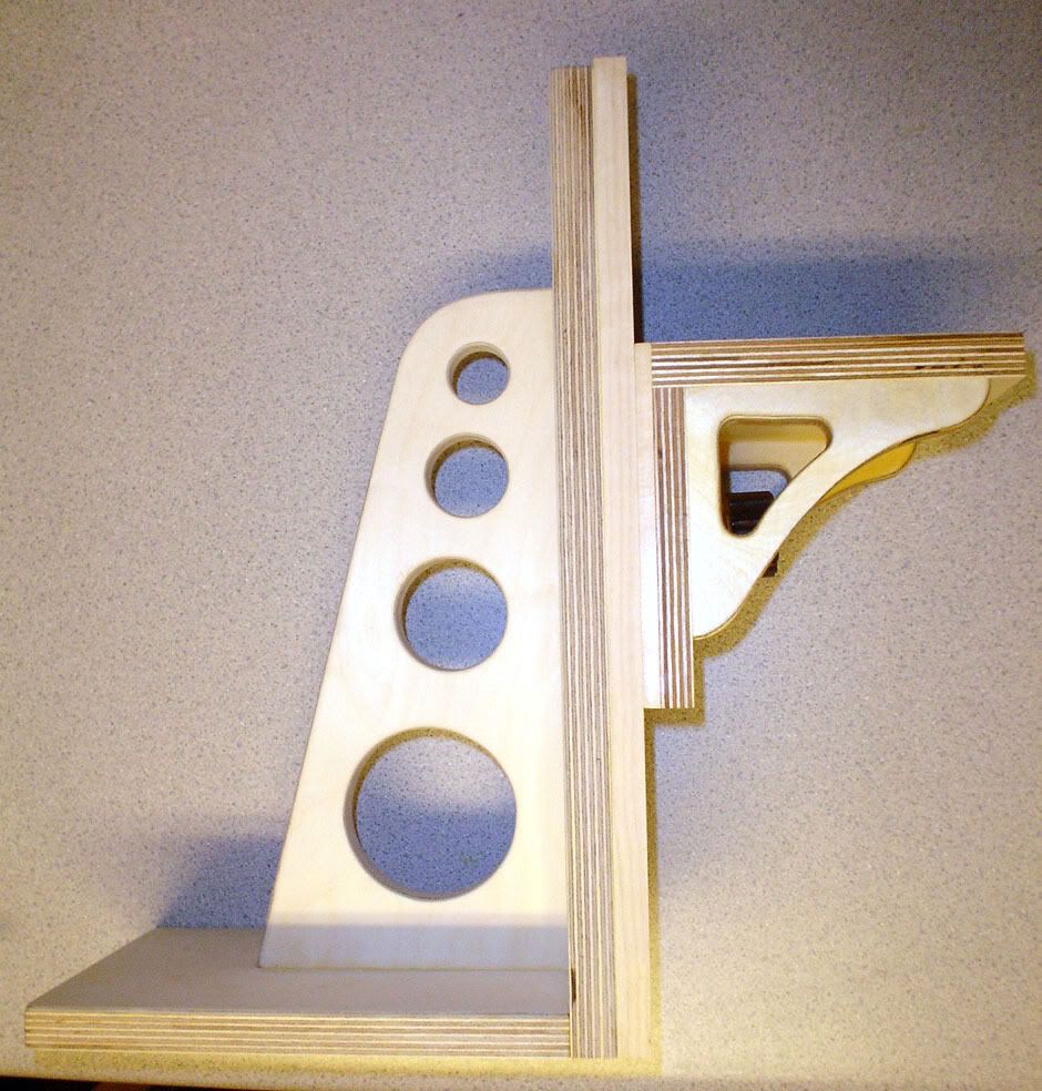 |
|
|
|
Post by Steve Austin on Jan 7, 2007 21:07:56 GMT -8
Geep, Nice job of the angle bracket and I like the additional lightening holes that you placed in the spine of the bracket and the angle head. What I am finding with the angle bracket is that it is a little light when any weight is placed on the angle head. The only way to compensate this is to add additional weight to the base of the bracket. I might add a perimeter to the back of the base to house a blank of steel to give it the additional weight for stability. This will counter balance the bracket when using a scribing mouse on the scale model. Have you any thoughts on this? Steve  |
|
geep
New Member
Posts: 26
|
Post by geep on Jan 8, 2007 10:00:58 GMT -8
Hi Steve, I noticed that when I first test-fit everything. Here's what I'm thinking about for my set: Route out a recess in the underside of the base about 3" by 4" and about 5/8" deep. Mask off the perimeter with 2" masking tape and waxed paper. Measure out some lead bird shot by filling the cavity just below the brim. Now mix the shot with some 1-hour epoxy and re-fill the cavity. Again, making sure it's just below the brim so the weight doesn't drag the surface plate. Stir to remove air bubbles. Allow to set. Be sure to 1-hour or slower epoxy. The fast-set stuff will exotherm massively when that much sets at the same time. It could cause a fire.  Instant weight block! It should add about 3 lbs to the back end. Thanks for the how-to, it made things much easier! It's obvious that a lot of time and thought went into them. I expect that they'll be in my tool kit for a long time.  -John |
|
|
|
Post by Steve Austin on Jan 8, 2007 12:59:52 GMT -8
Hi John, I initially thought about routing out the base also but I didn't want to upset the integrity of the bracket. With the metal plate screwed on top of the base and even shaped around the spine it should give the weight required but the lead shot is a great way to go and keeps the aesthetics of the angle intact. My main concern would be keeping the base flat. It would be easier adding weight to the top, be it routing down and shuttering the perimeter of the base to keep the edges flat, at least the base is untouched. I will have to spend some more time thinking about any other alternatives but either way would be a good solution. Post some more photos once you have your brackets done and I'll do the same once I've decided which way to go. Steve |
|
geep
New Member
Posts: 26
|
Post by geep on Feb 5, 2007 18:07:24 GMT -8
Today I routed out the bases and filled them with lead. Here are during and after photos: 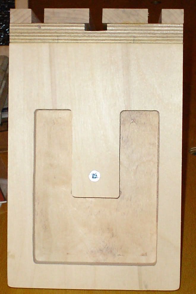 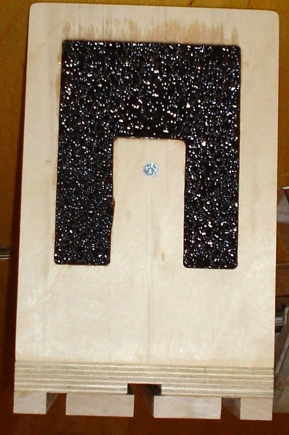 The process went well. I found that it is easier to add the epoxy into the cavity, then add the #9 lead birdshot and mix thoroughly. Mixing in the can and transferring to the cavity results in a poor bond between the lead and the wood base. The cavity is .5" deep and adds about 2.2 lbs to the base. It is sufficient to make the angle brakets much more stable. Later on, depending on how the bases wear I might add a 1/4" maple "shoe" to the base to cover up the lead. Now all that is left is to finish sand everything and apply the polyurethane. |
|
|
|
Post by Steve Austin on Feb 6, 2007 7:20:36 GMT -8
Hi John, It looks like the lead filling went pretty well. Nice and clean with enough weight to do the job. I might have to do the same myself. Steve |
|


