geep
New Member

Posts: 26 
|
Post by geep on Nov 16, 2006 22:43:03 GMT -8
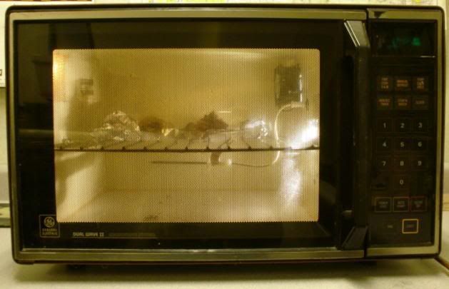
This spring, when I got started with industrial clay, I was planning to buy a used bun warmer from a commercial kitchen supply. At least until my old microwave died. The microwave, a massive GE unit popular in the mid '80's, had one nice feature: A temperature hold function for cooking turkeys and ham.
Microwaves vary the temperature of the food by adjusting the duty cycle of the magnetron, basically turning it on and off. This is perfect for a clay oven heated with lightbulbs.
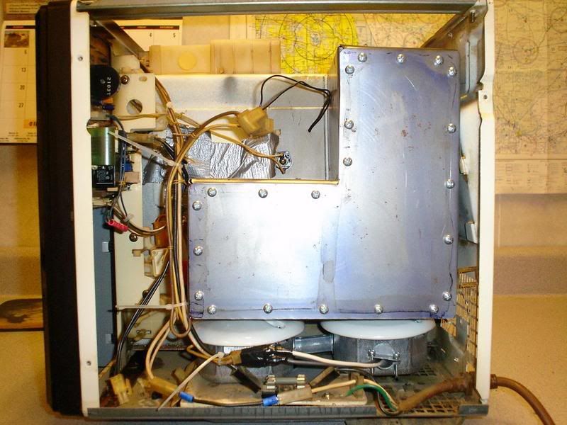
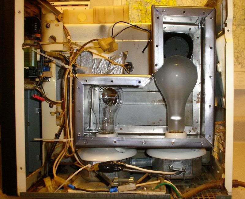
What I did was remove the magnetron and associated cooling fan and heatsink. In its place I installed two ceramic keyless lampholders rated for 600 watts. Around this I bent up a sheetmetal box with a door to access the light bulbs inside. The other half of the box backs up to the cooking cavity. A few holes between the bottom and top of the box and a small 120 V fan serve to circulate air between the ample space of the cooking cavity and the lightbox. One 150W and one 300W lightbulb serve as the heat source.
The neat thing about this modification is that it's plug-and-play. Plug the lightbulbs in parallel to the magnetron relay and the fan to the magnetron cooling fan relay. A little sheetmetal bending and it's ready to go. Result: A clay warmer that will hold +- 2F in under a day! The best part is it was free!
I'll try to post some photos in the next day or two.
Specs:
Capacity: About 50 lbs.
Warmup time: 140F in under 5 minutes.
Cost: About $10 for lightbulbs and misc parts
|
|
|
|
Post by Steve Austin on Nov 17, 2006 7:52:11 GMT -8
Hi John,
One of the most asked questions that I get is where can I get a suitable oven at a reasonable cost and your improvisation of the microwave oven sounds just the ticket. If you could place some detailed photos for the other guys it would be a bonus.
The second hand stainless steel bun ovens that you can get from restaurant supplies are still expensive for someone who is starting clay as a hobby.
On your microwave is there a thermostat for heat control or is it just the lamp output with the fan that keeps the temperature approximate?
|
|
geep
New Member
Posts: 26
|
Post by geep on Nov 17, 2006 19:52:16 GMT -8
Hi Steve,
I would be happy to put together a few photographs and some basic instructions on the conversion process. Anybody with a decent supply of hand tools should be able to do the conversion for under $50 in less than 8 hours.
Temperature control is via varying the duty cycle of the lightbulbs. Simply enter the temperature you wish to hold, then hit start. When the oven warms to temperature the bulbs switch off. Once the temperature cools 2-4 degrees the bulbs turn back on again. It will hold +- 2 degrees in a range between 81F and 180F.
You're right on the bun warmers. I was ready to plunk down $500- $800 on a massive warmer until the microwave went south. I think it would have easily held 200lbs of clay. I'm not sure I could apply that much in a day. ;D
|
|
geep
New Member
Posts: 26
|
Post by geep on Jan 7, 2007 17:35:13 GMT -8
Hello again,
In my efforts to teach myself clay modeling, I've neglected to post the how-to for my clay warmer. I spent today putting together some text and a few photos on the subject. Hopefully, it will prove useful to new modelers.
Here is the text, photos to follow shortly:
How to convert a microwave into a practical clay warmer.
Version 1.0
By John Paulding
If you're just starting out in clay modeling, one of the biggest challenges is finding a suitable clay warmer. The challenge is finding a something that will accurately hold the low temperatures required. 140 degrees is well below the capability of toaster oven or similar cooking appliance thermostats to regulate. Many modelers end up making a plywood box, jury-rigging a thermostat to some light bulbs and calling it good enough. I originally considered this, but decided not to pursue this due to the possibility of fire.
Those who don't wish to go the DIY route usually turn to the foodservice business and use a bun warmer. Used warmers are generally nasty, beaten up, and expensive. Brand new they can range into the thousands. As luck would have it, my microwave died just as I was in the process of negotiating on a heavily used bun warmer. The following write-up will show you how you can turn a similar microwave into a perfectly usable clay warmer in under 10 hours.
Step 1, The Basics
Before we begin, I think it's important to get some terminology straight. A microwave cooks food by bombarding the water molecules with microwave energy. This energy is generated by a device called a magnetron. The magnetron is driven by a high voltage power supply. Power is supplied to this transformer by a relay controlled by the microwave computer. The output power of the magnetron is fixed, however the amount of energy transmitted to the food can be varied. The "power level" adjustment is actually an adjustment of the duty cycle of the magnetron. Duty cycle refers to the percentage of time that the magnetron is transmitting. For example, a magnetron that operates 1 minute out of ten is said to be operating at a duty cycle of 10% If it operates 10 minutes out of 10 minutes it is said to operate at a 100% duty cycle.
Why is this important to warming clay? This incredibly simple way of controlling the temperature of your food can be adapted for use in warming clay! By substituting several large light bulbs for the high voltage power supply and magnetron we have a controlled heating source. By using the food temperature probe to determine the temperature within the cooking chamber the computer can accurately regulate the temperature within the warming cavity. The result is a highly accurate regulated temperature oven perfect for warming small batches of clay.
Step 2, Finding a Nuker
Before we can begin, we need to find a suitable microwave. I used a General Electric model JE-1445. The JE-1445 and JE-1455 microwaves were common in the early to mid 1980's. Built like a tank and totally user-serviceable, most parts are still available through GE. One handy thing about early microwaves is the schematics were normally included in the owner's manual or inside the microwave cover. The cooking cavity measures 11" x 16" x 13", sufficient to hold up to 50lbs of clay. Power output was 700W at 120V input. The temperature hold function is operable between 80F and 180F.
It is not required that you find a JE-1445 to use this instruction, just about any microwave with temperature hold function will work. To find a suitable microwave, I suggest you check the yellow pages for an appliance repair company in your area. Although appliance repair companies are becoming very hard to find in this day of throw away products, they can still be found in some larger cities. In addition to the temperature hold function, the microwave should be of sufficient capacity for your needs and have an operable computer. Be sure to obtain the temperature probe with whatever microwave you find. This is crucial to building your clay warmer.
NOTE: It is possible to build a microwave clay warmer that does not use a temperature probe. However, it would be necessary to manually adjust the duty cycle of the heaters using the microwaves power level control on the front panel. It’s not as efficient as a temperature probe machine, but it will work. To adjust the temperature it will be necessary to make an equilibrium temperature chart which correlates positions on the dial with cooking chamber temperature. Reference the chart to determine the duty cycle required, set it, forget it.
Step 3, The Conversion
BE SURE THE APPLIANCE IS UNPLUGGED BEFORE BEGINNING!
DISCHARGE THE HIGH VOLTAGE CAPACITOR! Do this by shorting across the terminals with an insulated screwdriver. The capacitor will generally be an oval can, approximately 1" x 3" and 4" or so tall. Failure to do this could result in a severe shock. The capacitor could still have many hundreds of volts of charge even if the machine has been unplugged for a significant period of time.
Tools required:
Phillips and flat screwdrivers
Pliers
Wire cutters/stripper
Hand brake AKA “hand seamer”
Assortment of hole saws
Hand drill and drill bits
Tin snips
Multimeter (as required to diagnose faults)
Thin Sharpie marker
Combination square
Ruler
Prussian blue
Sharp scriber and layout dye. (dye optional depending on preference)
Dead blow hammer or similar, plastic
3x 4" C-clamps or equivalent
3x 3/4" x 4" x 1' hardwood
Supplies required:
Two keyless PORCELAIN light fixtures suitable for at least 300W
Two octagon boxes
One 1/2" offset or straight EMT nipple
One NM connecter, or a rubber grommet to fit a 1/2" knockout
One Radio Shack 120V computer fan, Catalog # 273-242 or equivalent
#12 high temperature wire
Zip ties
#8 x 1/2" pan head sheet metal screws
#8 x 1 1/2" pan head sheet metal screws
Sheet metal, approx 3' x 3', 20 to 26 ga.
At least one 150W and one 300W light bulb
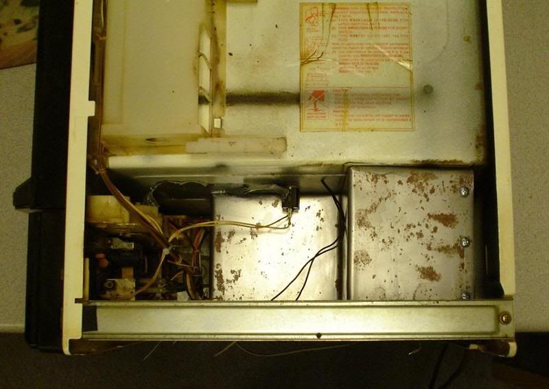
1) Now that you have a microwave in hand, let's start by removing the covers. Once inside, begin by discharging the high voltage capacitor (see above). Now locate the schematics and service information packet. These should be secured to a flat surface inside the cover or on the cooking cavity. You'll need these later.
2) Locate the high voltage power supply and magnetron. Begin by marking the input power wires to the high voltage power supply. These will become the switched lines for the light bulb heater. Disconnect and remove the power supply, HV capacitor, and magnetron. Also locate the magnetron and oven thermal cutouts. Bypass or remove these as required.
3) Locate the magnetron cooling fan. Mark the wires supplying power to the fan and disconnect them. Remove and discard the magnetron cooling fan.
4) If your microwave doesn't have a turntable it will have what is called a "stirring motor". This motor turns the waveguide assembly (microwave antenna) to ensure that the cooking cavity is evenly saturated. The stirring motor is not required for warmer service, so locate it's power supply wires and disconnect it. Terminate the wires in compression terminals to prevent shorting. You will likely be unable to remove the actual motor without significant disassembly of the microwave frame, this will not affect operation.
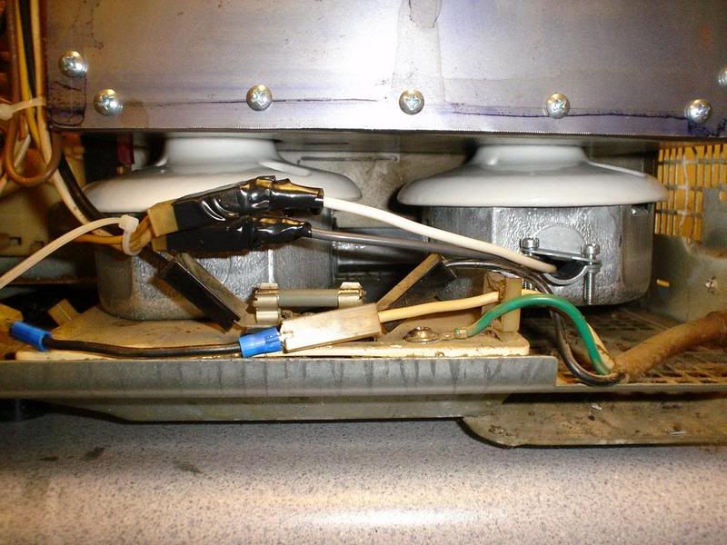
5) Now that you have the un-needed equipment removed, find a suitable location to mount two octagon boxes and two keyless light fixtures. The octagon boxes should be mounted side-by-side on a flat surface as close to the cooking cavity as the projection of the keyless fixture will allow. The two boxes should be connected together by the EMT nipple. Be sure there is sufficient room to mount the light box around the light bulbs. Experiment with different locations before screwing them down with several #8 sheet metal screws.
6) Now wire the fixtures. Wire them in parallel to ensure that both light bulbs receive full line voltage. Although the temperature inside the octagon box doesn’t seem to exceed 100F, I suggest you use a conductor rated for at least 300F. Your local electrical supply can help you with this. Be sure to make mechanically as well as electrically sound connections.
Now that you have the fixtures wired, connect the light bulb heaters to the power supply wires you disconnected earlier. Close the oven door, plug in the microwave, and test that your circuit works by installing both light bulbs and doing a time cook. You should hear the main power relay click and the light bulbs should light. If the main power relay clicks but the light bulbs do not light, check your wiring. If the main power relay doesn't click check the door interlocks per the service instructions.
7) Now that you have the light bulbs working it's time to bypass the interlocks. Most microwaves I've encountered have three interlocks. One signals the computer that the door has been opened canceling the cooking cycle, one directly disconnects the magnetron power supply from line voltage, and one switch shorts the input lines of the power supply. On my particular oven the only switch that you must circumvent is the primary interlock. This switch signals the computer that the oven door has been opened and the computer responds by ending the cooking cycle. Not very handy when you open and close the door to get clay! Defeat this switch by clipping the wires and splicing them together. I left the other two switches in operation. This shuts off the lights and stirring fan when I open the door, but because the computer does not cancel the program they come back on as soon as I close it again.
8) It's now time to interface the light box with the cooking chamber. Begin by installing your light bulbs again. Now trace a box onto the cooking cavity large enough to encompass them while leaving at least 1" of clearance in all directions. The box should extend approximately 1/4" below the neck of the bulb socket of the keyless fixtures to allow them to project into the light box. A small combination square will help to transfer these points to the cavity wall. Be sure to leave plenty of clearance above the bulbs for replacement!
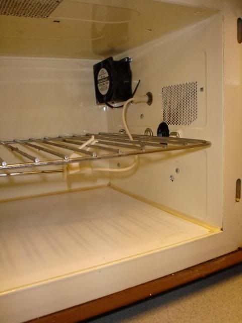
9) Now that you have the outline of your box set up, trace another outline 1/2" inside it. This is the inner limit of the mounting flanges of the light box, cut two holes within these lines with a hole saw. One hole should be as close to the bottom and as far away from the fan location as possible. This will be the light box intake hole and should be roughly 1 1/2" in diameter
Now locate the fan you purchased and measure it to determine the hole size required. The Radio Shack Catalog# 273-242 requires a hole 3 1/2" in diameter. Cut this hole as close to the top as your inner lines will allow. Now mount the fan inside the cooking cavity to suck air from the light box into the cooking cavity. I suggest #8 x 1 1/2" sheet metal screws for mounting. Drill the fan mounting holes as required to fit the screws.
Connect the fan wires to the magnetron cooling fan power supply wires. This will switch the fan on and off with the light bulbs on a separate circuit. Plug the microwave back in and test to see that the fan and light bulbs operate.
10) All that's left now is to make the light box itself. To do this with a minimum of tools I suggest you obtain two strong and square pieces of hardwood approximately 3/4" by 4" by 1'. By securing the sheet metal between the wood and clamping everything to a workbench it's possible to bend the metal with reasonable accuracy.
Proceed as follows:
10a) Layout the main trace marks you made back in step 8 1:1 on a piece of paper. Measure the total exterior circumference and add 1". This is dimension A. Now measure the depth of the box, allowing for 1" or so of clearance around the lightbulb. This is dimension B. Now cut out a section of sheet metal dimension A long and dimension B +1" wide.
10b) Starting from a top corner, scribe off the center of every bend onto the sheet metal. Scribe lines 1/2" from both long edges and one short edge. These will show where to bend the tabs in.
10c) Drill a 1/8" hole at the apex of every bend. Then cut a 45 degree relief notch that intersects the hole. This is to allow relief for the mounting tabs.
10d) Begin bending up the box. This is a trial-and-error procedure based on the box design. I suggest you practice with scrap sheet metal first. Try to bend the mounting tabs in with a hand brake first. Then insert the section lengthwise in between your hardwood boards and clamp down. The scribe line should be approximately .050" from the edge of the board. Using your third board to distribute the blows from a dead blow hammer, begin making the bends. The scribe line should end up approximately 45 degrees though the bend. Adjust the setback (the distace from the board to the scribe line) as required to get the scribe line centered on subsequent bends.
10e) After completing the final bend cut off the excess metal. There will be some misalignment of the final panel and the tab due to the bend allowance, but calculating this is beyond the scope of this paper. Secure the final panel to it's tab with several short #8 sheet metal screws.
10f) Now that you have a box, let's mark the positions of the keyless fixtures. Begin by measuring the OD of the neck approximately 1/4" down from the top. Add 1/32 to this dimension and pick out a hole saw. Now take some Prussian Blue and apply it liberally to the top of the keyless fixture. Take your box, place it against the cooking cavity. Using the vertical lines you scribed on the cooking cavity as a guide, slide the box down until it touches the top of the fixtures. Push down hard!
Now remove the box and turn it upside-down. You should have two decent impressions of the top of the fixtures. Center the hole saw on these impressions and saw out the holes. Test fit and adjust with a file as required.
10g) Mount the light box with short #8 screws from the inside of the cooking chamber.. Make a cover from the layout you made back in step 10a and attach it. If everything fits you're ready for a test!
11) Install the light bulbs, plug in the temperature probe, set the computer to hold 140F and hit start. It should reach 140F in 5-7 minutes. If this works, you're good to go! Put the covers back on and post a photo!
If you have problems try troubleshoot them individually. Attempt to isolate a common fault. Be sure that the interlock switches aren't causing problems. If nothing works, check the fuse. Microwave fuses are special fast-acting types and are very sensitive to current fluctuations.
|
|
geep
New Member
Posts: 26
|
Post by geep on Jan 7, 2007 18:33:27 GMT -8
|
|
geep
New Member
Posts: 26
|
Post by geep on Jan 7, 2007 18:48:18 GMT -8
Here are the schematics for the JE-14xx series. They will help with locating wires and troubleshooting faults. I also have instructions related to troubleshooting the control logic. If anyone needs them, contact me. 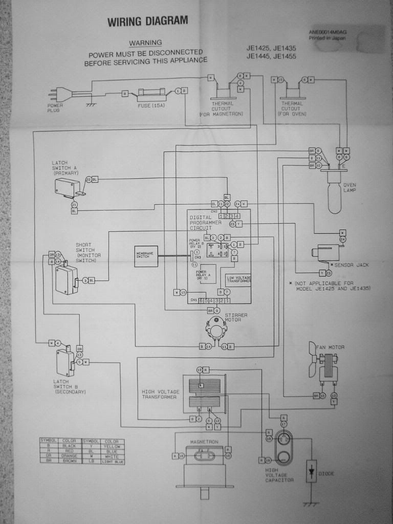 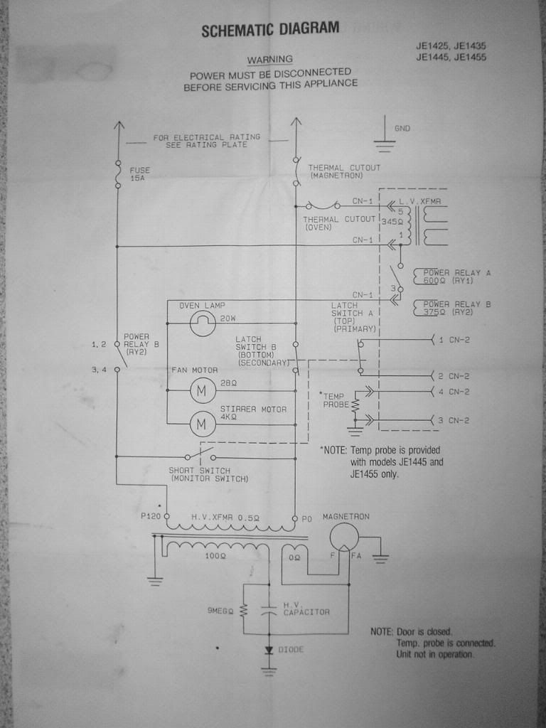 |
|
|
|
Post by Steve Austin on Jan 7, 2007 21:33:51 GMT -8
John, Nice details on the microwave conversion. I'll be interested to see if any of the other members come up with their version also. I have my own bun oven but this is certainly a fall back option and definitely takes up less space and probably more effective. Certainly one of the most constuctive posts on this forum. Good job! Steve  |
|