geep
New Member

Posts: 26 
|
Post by geep on Nov 13, 2006 23:58:47 GMT -8
Hello, This is my first post, so an introduction is in order. I found styling clay as another tool to use when developing patterns for my composites business. I was looking for a material that would allow me to quickly and accurately reproduce compound curves, while making it possible to revise the pattern if required. My search began with Sculpey modelling clay. I liked the fact that it would become a solid mass when baked, but was unsure about the dimensional stability as it cured. I shouldn't have worried, the body of the clay is so soft that it is impossible to define a shape. This became obvious when I tried a little experiment: 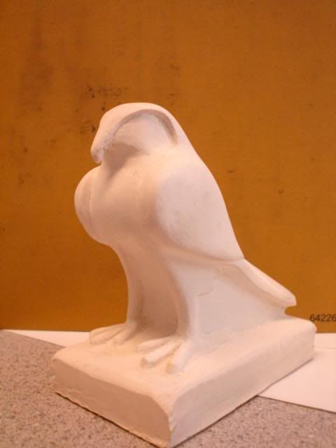 Although the shape is resonably well defined, it was impossible to get the sharp features I was looking for. In addition, the soft nature of the clay made holding a tolerance impossible due to flex. I knew that the automotive industry was using clay for modelling purposes, and a few hours on the internet turned up this website and the Chavant company. (Thanks to Steven for the good info on this page.) I ordered a few of their videos, a tool kit, and 60lbs of I-307. Now to my question: After practicing on smaller objects for several months, I have decided to do a full-scale test. For my test I thought a new tank for my motorcycle would provide enough modelling practice without getting overly complicated. I made a few rough sketches of the desired shape. This is one of the rough sketches: 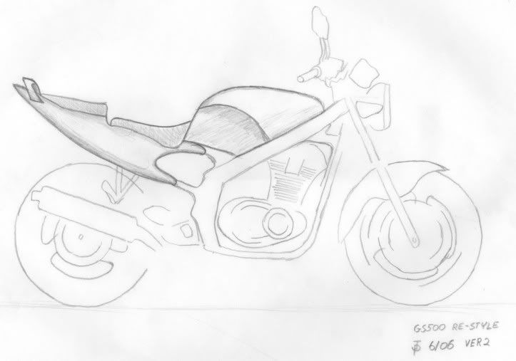 The top and rear views aren't critical, because the horizontal plane is governed mainly by the shape of the frame. The details will be governed by what looks good, and how it feels. I plan to rough to my sketches with templates, then revise the shape freehand. Since the tank is symmetrical about the longitudinal axis my plan is to model only one half of the tank initially, using a mirror to show the other half. Once I have the final shape I will model the other half to match. How should I go about modelling the other half to a reasonable degree of accuracy? I would like to stay within +- .030, as I will be taking a mold from the finished clay model. My original idea was to place the half-finished model on a surface plate and use a height gauge to trace the shape onto mylar at various intervals. I could then make templates from the sections to model the opposite side. Are there any other methods that might be faster or more suitable? Am I making this more complicated than it needs to be? Regards, John |
|
|
|
Post by Steve Austin on Nov 15, 2006 8:04:41 GMT -8
Hi John, I think you have the general concept on how to approach your tank modeling project. I would include in your modeling kit a set of profile gauges such as the ones on my web page. www.claysculptors.com/profile%20gauges.htm This will help to achieve the duplication of form in the more sculpted areas. Grid the finished half and transfer the most critical points over to the secondary side then bed your templates to suit. The profile gauges can then be used to finalizes any areas that are vague. Make sure to gut the feature line in the side of the tank to hold it crisp. This will be the critical line for symmetry, if this is dimensionally correct everything else should fall into place. Have fun with your project and post some pictures as you progress. Steve  |
|
|
|
Post by samstheman on Nov 15, 2006 9:42:53 GMT -8
It looks like you did your research good job.I think you have half the battle one by just having a clear approach or design to what your modeling. As long as you keep a very accurate centerline on your surface and an accurate lowest base or Plainview line balancing will be easier so you have some points to work from and keep all the edges sharp no radius till you balance its easier to work from a sharp line and add all radius last. Good luck and post some pics. In case you didn't know gut is fishing line use a knife to cut in to surface slightly and put fishing line in grove then when you clean the clay it will hold a very sharp edge.
|
|
geep
New Member
Posts: 26
|
Post by geep on Nov 16, 2006 23:46:32 GMT -8
Thanks for the tips. I'll order a profilemeister set in the next day or two. It looks significantly better than the home depot variety.
Thanks for the clarification on gut lines. I figured that was what Steve was referring to, but wasn't sure. I saw fishing line being used as a guide for wires in Chavant's basic clay modelling video. I'll certainly be using that for the main feature lines.
I'm sure to be asking plenty more questions as I get underway. Should have photos in a week or two. I have to finish up some other things first.
|
|
geep
New Member
Posts: 26
|
Post by geep on Jan 8, 2007 15:00:13 GMT -8
Update: I got a package from Chavant a few days ago. In it was the 5 pc. Profilmeister gauge set from along with their advanced modelling video (I already have the other two) and Yamada's book. The Profilmeister gauges are so much better than the garden variety hardware store specials. Can't wait to try them out. The armature is roughed in and ready for foam. I'm reviewing a few different shapes for the tank/rider interface. As soon as I decide what works best I'll begin the full-size key line drawings. Slowly but surely...  |
|
|
|
Post by Steve Austin on Jan 9, 2007 7:34:02 GMT -8
John, When you have one side of the tank modeled and you are duplicating via Profilmeister gauges, a strip of masking tape across the pins will prohibit them from moving when transferring the shape. That way you won't have to keep repositioning the gauges on the masterside. In the long run it will reduce the amount of damage to the surface. Steve |
|
geep
New Member
Posts: 26
|
Post by geep on Jan 30, 2007 10:05:24 GMT -8
Time for another update. I've been busy working on a modeling table, but I do have the 1/4 scale key lines almost complete: 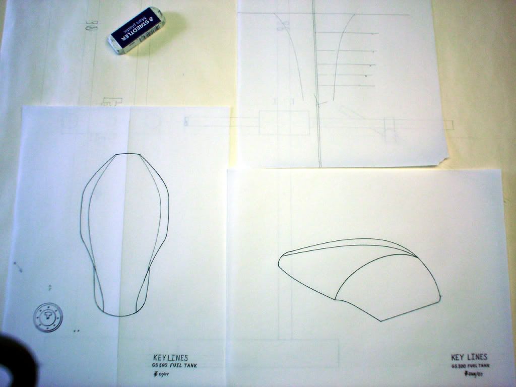 I expect them to change once I start the model. Especially the intersection of the top accent line with the front edge of the tank. The drawing at the upper right is the contour for the knee cutout. I still need to make a rear view, but that shouldn't take too long. I may also increase the "scroll" of the knee cutout line in the side view so it intersects the base of the tank at a slightly acute angle. I think the top view flows, but the side view needs a little work before I go full-size on Mylar. |
|
|
|
Post by Steve Austin on Jan 31, 2007 11:37:22 GMT -8
Hi John, The key to this design is being able to install the model onto the motorcycle for a test fit. The lines and form need to meet your requirements prior to a hard part being made. That means installing the fixing hardware to the clay model for installation to the motorcycle so that adjustments can be made on the fly, then removed for balancing. This additional step will ensure a custom fit. Steve |
|
geep
New Member
Posts: 26
|
Post by geep on Feb 1, 2007 13:21:09 GMT -8
Hi Steve, That's the plan. I built an armature that will fit in place of the existing tank. I've marked the centerlines of the armature and the motorcycle so I can reference them on the surface plate. Here's a photo from last week: 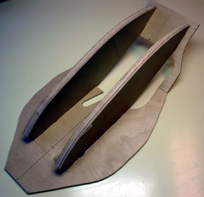 I still have to add some reinforcement and fill it out with foam. The cutouts are to clear the carburetors, throttle cable, and valve cover. I plan to rough in my key lines with templates, then stand back and see what I have. Then I'll pull out the wires and rakes and fine-tune it. That's the plan anyway. We'll see how long it lasts! ;D |
|
|
|
Post by Steve Austin on Feb 1, 2007 21:58:01 GMT -8
Hi John, Looks like you've got the backbone of the job done, once the foam is glued in place you will find that the armature is very rigid. What glue are you going to use for the foam as there are many available on the market? In most of my applications I have used gorilla glue because of the additional strength. The only thing to worry about is the expansion and this can be kept in check by clamping the foam while the glue cures. You will be able to see this very soon when I have the web page finished for the next part of the armature build on the website. I'm looking forward to seeing how the tank turns out. Steve |
|
geep
New Member
Posts: 26
|
Post by geep on Feb 1, 2007 23:20:05 GMT -8
Hi Steve,
I like a clear, heavy viscosity, 5-minute epoxy made by "System Three". It's great for quickly gluing things up where the glueline thickness isn't important. In fact, I used it to frame in the armature. It comes in 1-quart kits for around $37.
I have passed Gorilla Glue in the store several times, but I've never used it. I'll give it a try when I glue down the foam.
|
|
|
|
Post by Steve Austin on Feb 2, 2007 21:29:35 GMT -8
John, With the Gorilla glue water is the catalyst for setting the chemical change in motion. With a lot of the glues they are solvent based and will eat into the foam due to the exotherm involved causing a void in the gluing surface. I have used contact adhesive, used very sparingly to eliminate the melting of the foam but the glue joint then suffers. The only thing with the gorilla glue is it does get hard but providing there is plenty of clay coverage there is no problem. It gets a little tough when you have to cut it back. Steve |
|
geep
New Member
Posts: 26
|
Post by geep on Feb 19, 2007 20:11:06 GMT -8
Hi Steve, I managed quite a bit of work on the fuel tank model this weekend. I applied foam to the armature and carved it to rough shape, built a plinth to mount the armature to the table, made side templates from 1/4" tempered hardboard to form the top contour, measured the existing tank, and develped a true sweep to bed in the top surface. Earlier in the week I went to the hardware store in search of Gorilla Glue. While looking for Gorilla Glue I found Titebond Polyurethane glue, which appears to be a functional equivalent to Gorilla glue. What clued me in to the similarity of the products was the color of the glue and the instructions, which were exactly the same. The only difference I could find was the price, with the Titebond product being half the price of the Gorilla product! I see now why you like foaming polyurethane glue so much. The foaming properties allow it to bridge large gaps in the foam work, making precision cuts less important. Not only that, but it cuts MUCH more easily than epoxy. Less hassle too, as there is no mixing required. Thanks for the excellent suggestion! Tomorrow I'm going to smooth out the foam, make the bottom guide template, the side template and the knee cutout templates. Then I'll be ready to begin the real modeling. I'll take some photos shortly. I'm looking forward to seeing the progress on your Corvette foam work. John |
|
|
|
Post by Steve Austin on Feb 19, 2007 20:20:32 GMT -8
Hi John, Your absolutely right the Titebond is essentially the same stuff but I say Gorilla Glue purely because people will remember the name where as Titebond Polyurethane glue is forgettable. Looking forward to seeing your work in progress. I've got one page of the foam armature build up live and I'm working on the second page as we speak. Steve |
|
geep
New Member
Posts: 26
|
Post by geep on Feb 25, 2007 9:25:28 GMT -8
OK, here are some photos of the progress to date: The first photo shows my completed plinth. 1/2" dowels in the base of the plinth key into 1/2" holes drilled in the table on 6" intervals. A few pieces of carpet tape will hold the plinth to the table to prevent rocking. 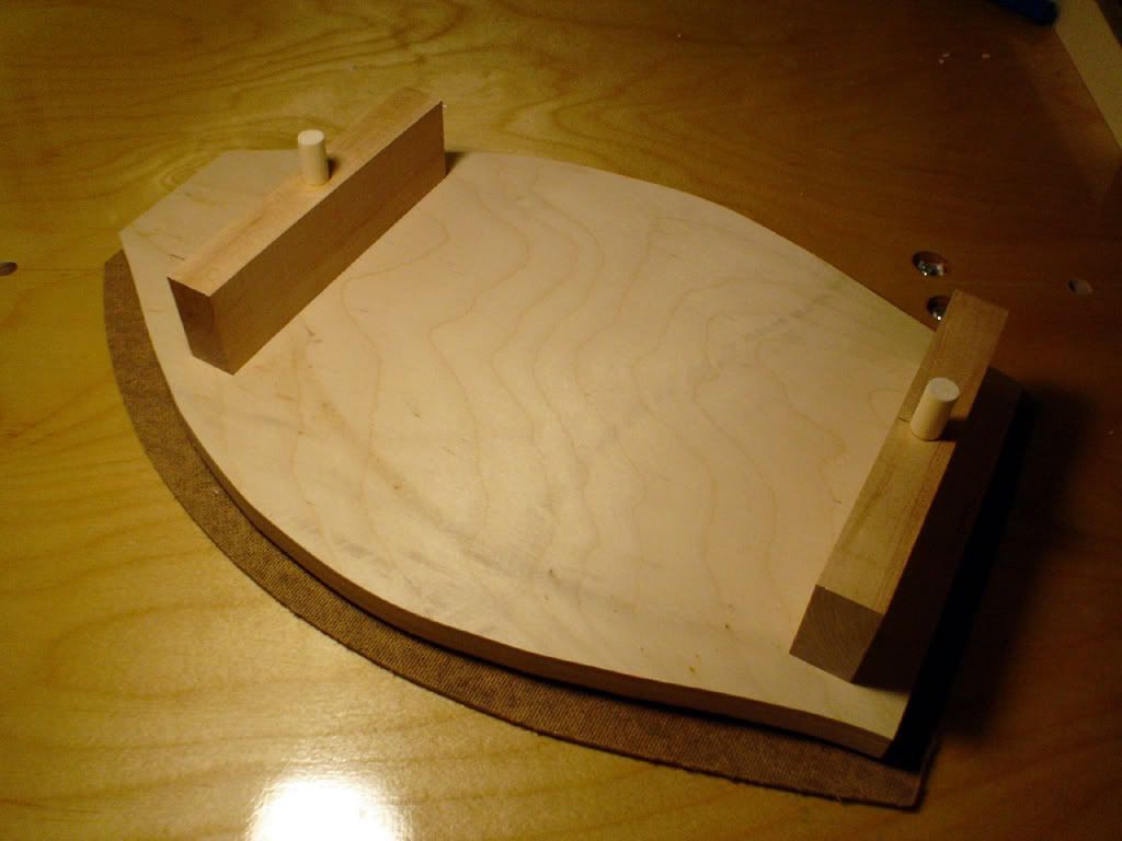 This photo shows the bottom guide template in place on the plinth. I wanted to line it up independent of the plinth, so I drilled clearance holes in the template. The bottom guide template is secured to the plinth with plenty of carpet tape. It will remain in place until the final step of modeling, which will involve extending the base to form a skirt for the mold. 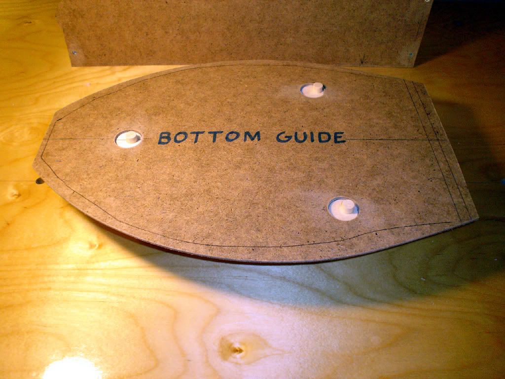 In these photos you can see the complete set of templates. In the back you can see the guide templates which will guide a true sweep to form the top surface. The clear plastic template is the true sweep, made from 1/8" Lucite with a radius of 15.25". Also shown is the side guide template to form the knee cutout profile, the curve to bed in the knee cutout profile, the side template, and the new seat. When the shape has been established, the front lip of the seat will be inset into the tank to form a flowing curve from the tank to the seat. 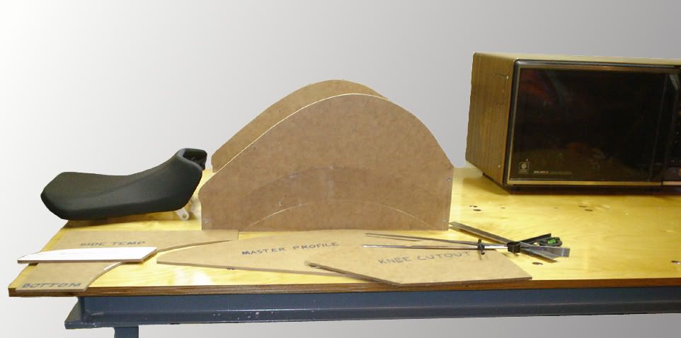 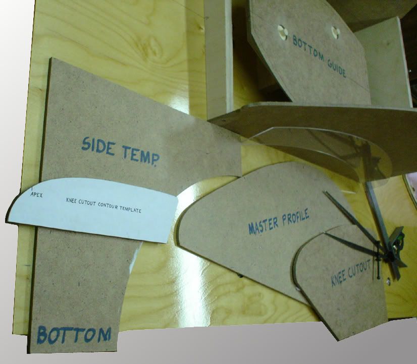 After lunch I'm going to begin applying clay. John Oh, do my photos appear dark on your end? I can't really judge the exposure on this monitor. |
|


