geep
New Member

Posts: 26 
|
Post by geep on Feb 26, 2007 0:18:17 GMT -8
Looking good!
Much cleaner than my foam work too. Mine looked hideous until I covered it with clay.
I like how you cut the foam to the full-size drawing. I limited my ability to do that with the design of my armature. The stiffeners in the middle made it difficult to piece the foam together around it while holding to a drawing.
In future, I'll make my armature easier to work with!
|
|
geep
New Member
Posts: 26
|
Post by geep on Feb 15, 2007 14:05:59 GMT -8
I'm looking forward to it.
|
|
geep
New Member
Posts: 26
|
Post by geep on Feb 1, 2007 12:42:48 GMT -8
Hi Steve, Adding metal contact plates to the underside of the table top is an excellent idea. I hadn't considered the possibility of a heavy model brinelling the plywood. I have a sheet of 18ga in the shop. I think I'll cut some squares out of that and install them between the plywood and the carriage bolts. I saw your table design and originally intended to go that route. However, I needed a larger glue-up table for wood patterns and that was enough to convince me to go the steel route. Being a small shop, I sometimes have a shortage of flat surfaces.  I tapped the leg bases 3/8-16. At the moment I have 3/8 x 2 carriage bolts installed to level it. However, at a later date I may install 3/8" threaded casters in place of the carriage bolts to aid in moving the table. I estimate the weight at about 200lbs. I just put the last coat of polyurethane on this morning. Here it is, ready for duty: 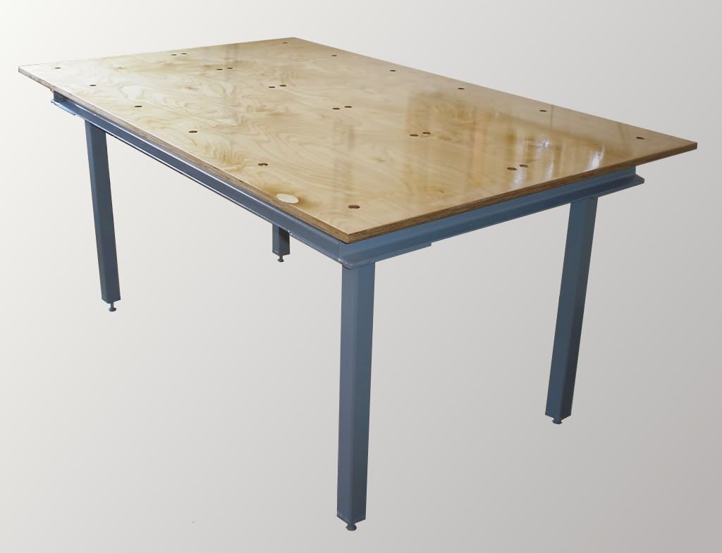 It doesn't show up very well in the photo, but I routed a 1/16" wide V-groove down the middle of the table to use as a center reference. Almost ready!  |
|
geep
New Member
Posts: 26
|
Post by geep on Jan 30, 2007 11:09:12 GMT -8
Last week I began work on a modeling table suitable for small to medium size work. Here are a few in-progress photos of my new modeling table and a description of the work to date. Design: I wanted a modeling table roughly 42" x 70" to accomodate smaller patterns. My main requirement was that it be strong, stiff, but not incredibly heavy as it will eventually reside on a wood floor. In my specification I chose 1/100th of an inch as an acceptable deviation from flat as measured across the width of the table. Down the length and corner-to-corner a slightly larger deviation would be acceptable. Due to the expansion and contraction of wood as the Equilibrium Moisture Content changes, I decided against all-wood construction. I wanted a wood surface to make securing plinths and models easy, but a steel frame to negate possible seasonal changes in flatness. Also, by building a steel frame it would be possible to incorporate an adjustment system to "tweak" the flatness of the table top. The Frame: I settled on a design made up of a 3" square tube backbone and a 3" channel frame. The square tube is very ridgid in torsion, which will prevent the table from racking. The channel makes joining the frame less complicated by using fewer welds. It also makes it possible for the CG of the welds to be arrayed around the CG of the section, resulting in lower distortion. An added bonus to the channel is it adds 1.5" of throat to the underside of the table for clamping purposes. 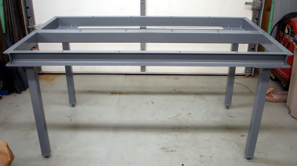 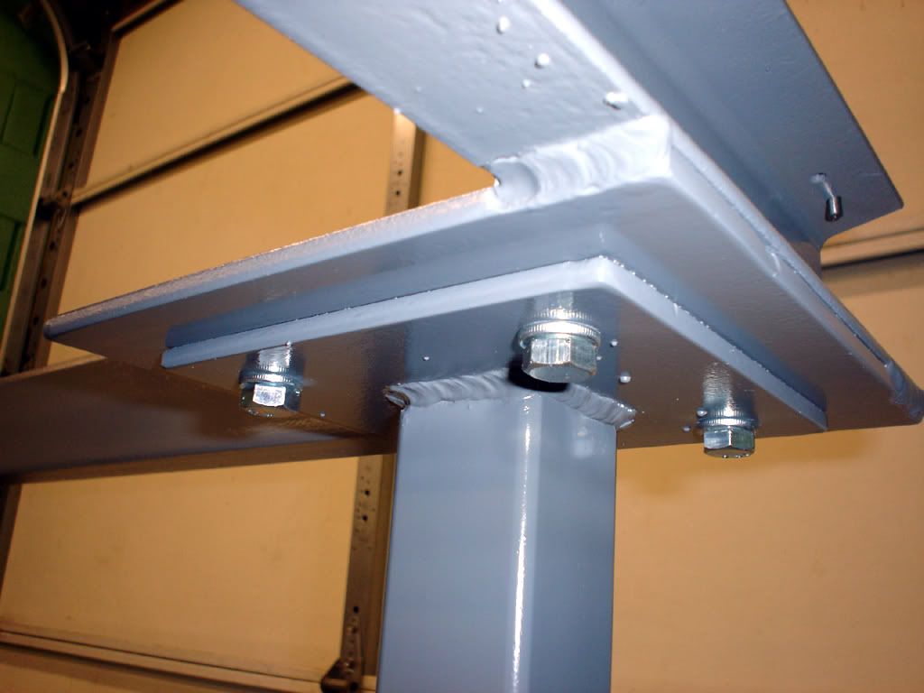 Materials for the frame: 20' 3" C-channel (frame) 5' 3" x 3" x 3/16" square tube (frame torsion spine) 10' 2" x 2" x 1/8" square tube (legs) 4' 1/4" x 6" flat (leg base) 4' 1/4" x 8" flat (frame stiffener/leg attachment base) 1' 3/8" x 2" flat (leg feet) Additional materials required: 2 cans Rustoleum primer 2 cans Rustoleum "Dark Machine Gray" enamel 24 1/4-20 sheet metal "back markers" 16 3/8-16 x 1 bolts 16 3/8 lockwashers Table top: I settled on 3/4" 13 ply baltic birch cabinet plywood for the top. It will be finished with 4 coats of polyurethane to reduce the seasonal variations in moisture content. The top surface will incorporate a centerline to aid in centering the model, and the four edges will be square and parallel to each other within 1/64th so that they may be used as guides. The top surface of the table will be drilled and counterbored to accept the 1/4" fasteners that to hold it to the frame. Underneath, 1/4" carriage bolts will apply preload up. Working in concert, the fasteners pulling down and the carriage bolts pushing up make it possible to adjust the height of the table at any location. To ensure that the holes in the table perfectly matched the threaded adjuster locations in the frame I decided to make some back markers specifically for the purpose. Shown below, the shaft of the marker fits inside the minor diameter of the internal thread. A flange prevents the marker from falling through and the pointed tip acts like a center punch, marking the center of the hole. 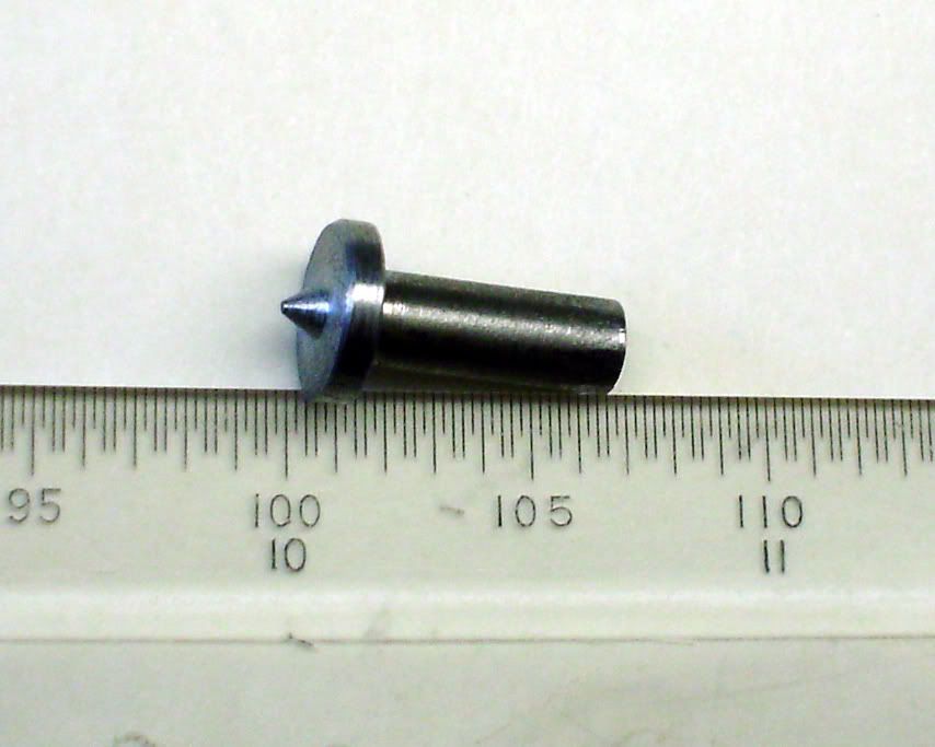 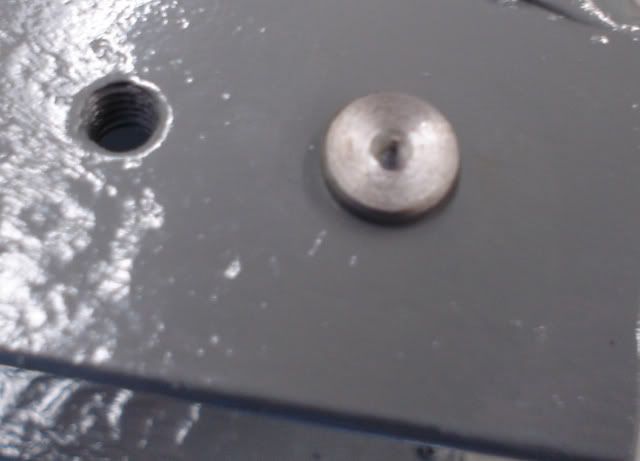 The markers actually worked better than I expected. Once the plywood was cut to size I marked the locations of the four corners and placed the table top on the frame. Then I weighted the top and marked each location by whacking the table top with a deadblow hammer. I placed a phone book approximately 1" thick between the table and the hammer to soften the blow and prevent marring of the surface. Here are a few locations that have been marked: 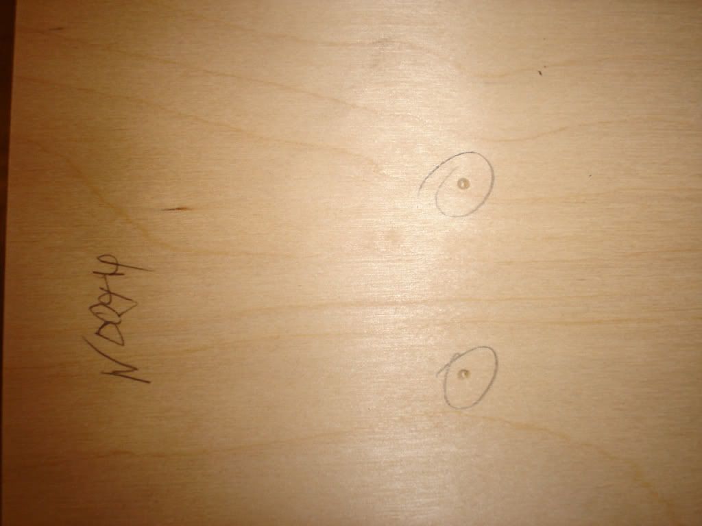 I'm currently applying a finish to the table top. I'll have more photos later this week. |
|
geep
New Member
Posts: 26
|
Post by geep on Feb 5, 2007 18:07:24 GMT -8
Today I routed out the bases and filled them with lead. Here are during and after photos: 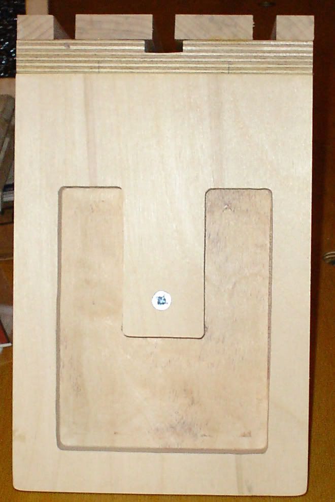 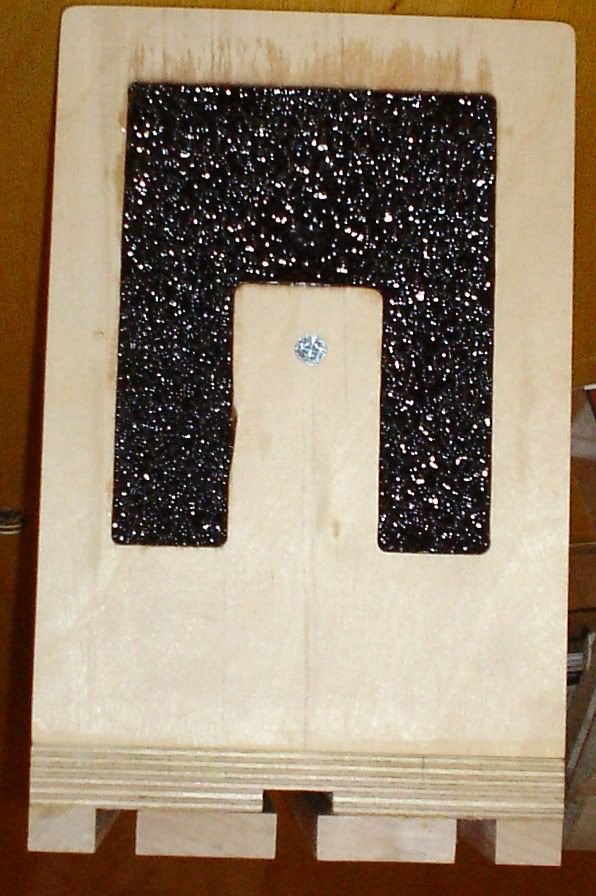 The process went well. I found that it is easier to add the epoxy into the cavity, then add the #9 lead birdshot and mix thoroughly. Mixing in the can and transferring to the cavity results in a poor bond between the lead and the wood base. The cavity is .5" deep and adds about 2.2 lbs to the base. It is sufficient to make the angle brakets much more stable. Later on, depending on how the bases wear I might add a 1/4" maple "shoe" to the base to cover up the lead. Now all that is left is to finish sand everything and apply the polyurethane. |
|
geep
New Member
Posts: 26
|
Post by geep on Jan 8, 2007 10:00:58 GMT -8
Hi Steve, I noticed that when I first test-fit everything. Here's what I'm thinking about for my set: Route out a recess in the underside of the base about 3" by 4" and about 5/8" deep. Mask off the perimeter with 2" masking tape and waxed paper. Measure out some lead bird shot by filling the cavity just below the brim. Now mix the shot with some 1-hour epoxy and re-fill the cavity. Again, making sure it's just below the brim so the weight doesn't drag the surface plate. Stir to remove air bubbles. Allow to set. Be sure to 1-hour or slower epoxy. The fast-set stuff will exotherm massively when that much sets at the same time. It could cause a fire.  Instant weight block! It should add about 3 lbs to the back end. Thanks for the how-to, it made things much easier! It's obvious that a lot of time and thought went into them. I expect that they'll be in my tool kit for a long time. -John |
|
geep
New Member
Posts: 26
|
Post by geep on Jan 7, 2007 20:02:18 GMT -8
Here's the nearly finished angle bracket: 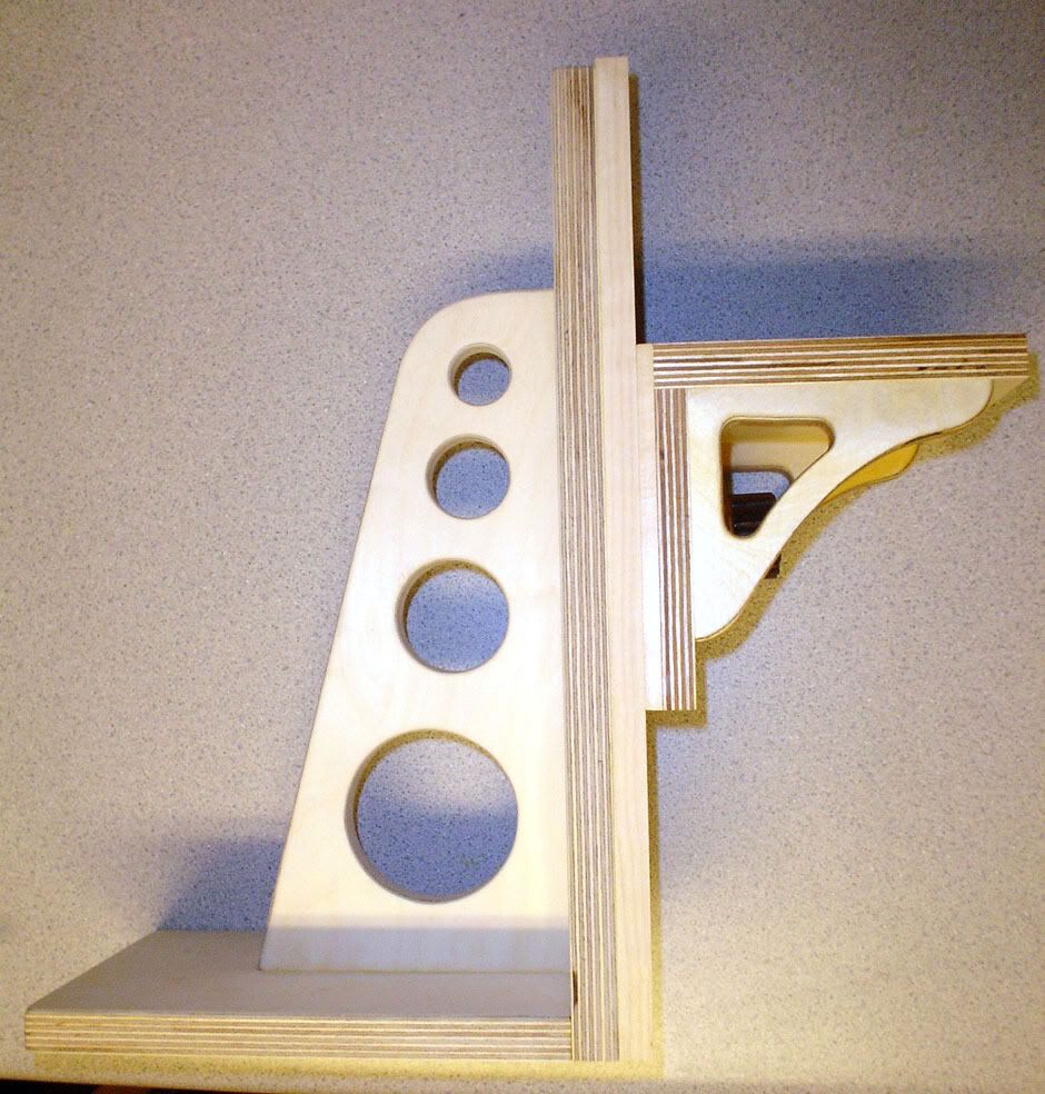 |
|
geep
New Member
Posts: 26
|
Post by geep on Jan 7, 2007 19:40:09 GMT -8
I decided to make a set of angle brackets per Steve's plans, which are very good. Working in my spare time I managed to get most of the parts roughed out and one knob made, and the parts for the other knob finished. Never being able to leave things alone, I've made a few "adjustments" in the construction just for fun. Here's the first knob: Materials prepared, maple for turning the shaft, walnut for the thimble and plug. 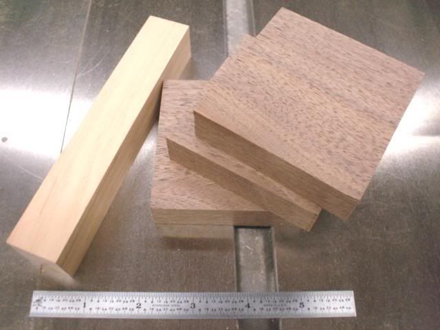 Using an oak spacer behind the walnut blank to prevent the boring bar from cutting the face plate.  Walnut blank mounted to the face plate. 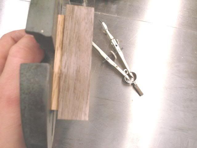 Marking the bore dimension. This will be fine-tuned to the maple barrel. 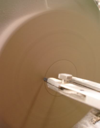 Boring the hole on a pattern maker's lathe. 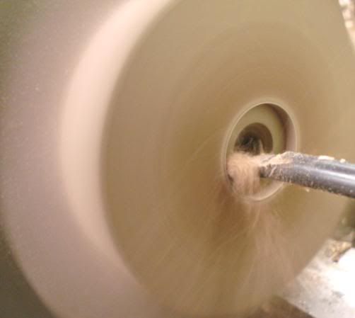 After drilling and chamfering the holes. 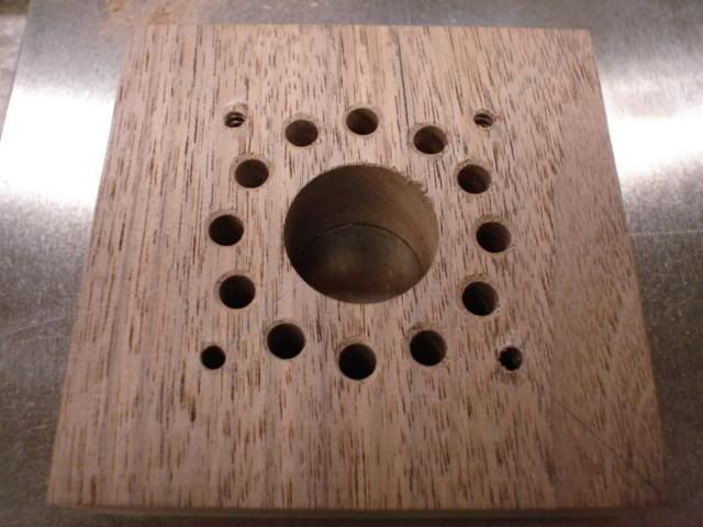 Cutting the knob out on a scroll saw using a spinning jig made from plywood and a scrap knob barrel. 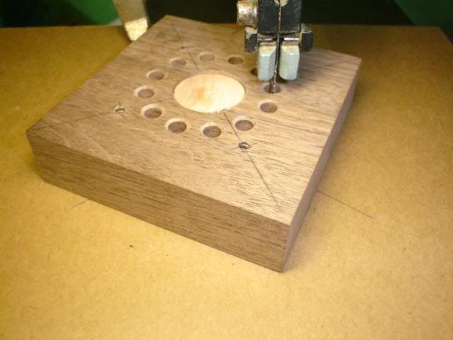 Ready for finish sanding. 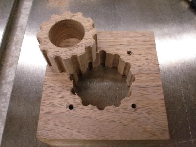 Parts ready to assemble. I used a machine set screw instead of a hex bolt. The hole was bored to rough depth, then I used a mortising machine to make the square recess for the screw. The walnut plug bottoms on the head of the screw. 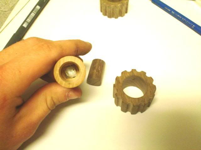 Finished product. 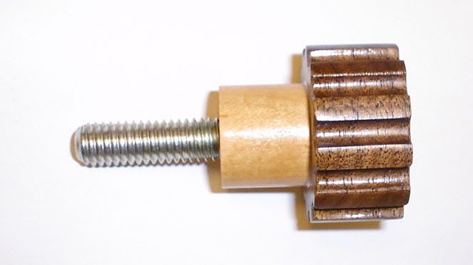 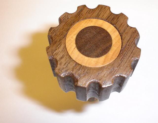 |
|
geep
New Member
Posts: 26
|
Post by geep on Nov 18, 2006 10:21:32 GMT -8
Interesting question. Machinery's Handbook is a little vague on S&F's for clay. ;D
As far as protecting the machine, the main things I would be concerned about are keeping the clay chips out of the coolant sump and protecting the ways. I would be sure to vacuum out the machine thoroughly before beginning, as you might then be able to salvage some of the clay swarf for re-use. A shop vac with a trash bag would be ideal for this.
To protect the ways, I would ensure that the way covers were tight and in good condition. This should prevent the clay from being ground between the sliding fits. I would take extra care in the case of a pressure-lubricated machine.
To prevent the clay from entering the coolant sump I would cover or plug the sump opening and stop the chip conveyor in the case of a machining center. Personally, I would prefer to do this on a toolroom machine, as you don't have to worry about as much cleanup inside the enclosure or chip conveyor. A sheet of plywood on the table would prevent the chips from entering the coolant via the table troughs and also provide some Z-axis overrun.
Just out of curiosity, why not rough the shape with drag templates? If it doesn't give away a new product, what are you modelling?
-John
|
|
geep
New Member
Posts: 26
|
Post by geep on Jan 7, 2007 18:48:18 GMT -8
Here are the schematics for the JE-14xx series. They will help with locating wires and troubleshooting faults. I also have instructions related to troubleshooting the control logic. If anyone needs them, contact me. 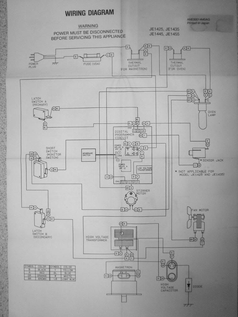 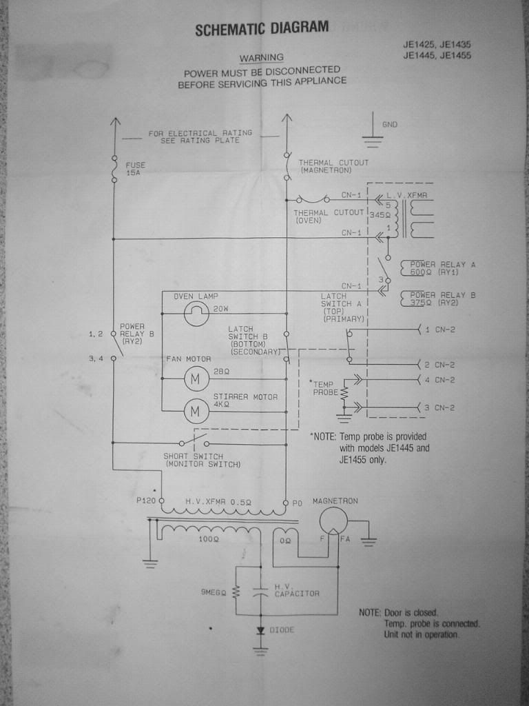 |
|
geep
New Member
Posts: 26
|
Post by geep on Jan 7, 2007 18:33:27 GMT -8
|
|
geep
New Member
Posts: 26
|
Post by geep on Jan 7, 2007 17:35:13 GMT -8
Hello again,
In my efforts to teach myself clay modeling, I've neglected to post the how-to for my clay warmer. I spent today putting together some text and a few photos on the subject. Hopefully, it will prove useful to new modelers.
Here is the text, photos to follow shortly:
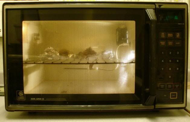
How to convert a microwave into a practical clay warmer.
Version 1.0
By John Paulding
If you're just starting out in clay modeling, one of the biggest challenges is finding a suitable clay warmer. The challenge is finding a something that will accurately hold the low temperatures required. 140 degrees is well below the capability of toaster oven or similar cooking appliance thermostats to regulate. Many modelers end up making a plywood box, jury-rigging a thermostat to some light bulbs and calling it good enough. I originally considered this, but decided not to pursue this due to the possibility of fire.
Those who don't wish to go the DIY route usually turn to the foodservice business and use a bun warmer. Used warmers are generally nasty, beaten up, and expensive. Brand new they can range into the thousands. As luck would have it, my microwave died just as I was in the process of negotiating on a heavily used bun warmer. The following write-up will show you how you can turn a similar microwave into a perfectly usable clay warmer in under 10 hours.
Step 1, The Basics
Before we begin, I think it's important to get some terminology straight. A microwave cooks food by bombarding the water molecules with microwave energy. This energy is generated by a device called a magnetron. The magnetron is driven by a high voltage power supply. Power is supplied to this transformer by a relay controlled by the microwave computer. The output power of the magnetron is fixed, however the amount of energy transmitted to the food can be varied. The "power level" adjustment is actually an adjustment of the duty cycle of the magnetron. Duty cycle refers to the percentage of time that the magnetron is transmitting. For example, a magnetron that operates 1 minute out of ten is said to be operating at a duty cycle of 10% If it operates 10 minutes out of 10 minutes it is said to operate at a 100% duty cycle.
Why is this important to warming clay? This incredibly simple way of controlling the temperature of your food can be adapted for use in warming clay! By substituting several large light bulbs for the high voltage power supply and magnetron we have a controlled heating source. By using the food temperature probe to determine the temperature within the cooking chamber the computer can accurately regulate the temperature within the warming cavity. The result is a highly accurate regulated temperature oven perfect for warming small batches of clay.
Step 2, Finding a Nuker
Before we can begin, we need to find a suitable microwave. I used a General Electric model JE-1445. The JE-1445 and JE-1455 microwaves were common in the early to mid 1980's. Built like a tank and totally user-serviceable, most parts are still available through GE. One handy thing about early microwaves is the schematics were normally included in the owner's manual or inside the microwave cover. The cooking cavity measures 11" x 16" x 13", sufficient to hold up to 50lbs of clay. Power output was 700W at 120V input. The temperature hold function is operable between 80F and 180F.
It is not required that you find a JE-1445 to use this instruction, just about any microwave with temperature hold function will work. To find a suitable microwave, I suggest you check the yellow pages for an appliance repair company in your area. Although appliance repair companies are becoming very hard to find in this day of throw away products, they can still be found in some larger cities. In addition to the temperature hold function, the microwave should be of sufficient capacity for your needs and have an operable computer. Be sure to obtain the temperature probe with whatever microwave you find. This is crucial to building your clay warmer.
NOTE: It is possible to build a microwave clay warmer that does not use a temperature probe. However, it would be necessary to manually adjust the duty cycle of the heaters using the microwaves power level control on the front panel. It’s not as efficient as a temperature probe machine, but it will work. To adjust the temperature it will be necessary to make an equilibrium temperature chart which correlates positions on the dial with cooking chamber temperature. Reference the chart to determine the duty cycle required, set it, forget it.
Step 3, The Conversion
BE SURE THE APPLIANCE IS UNPLUGGED BEFORE BEGINNING!
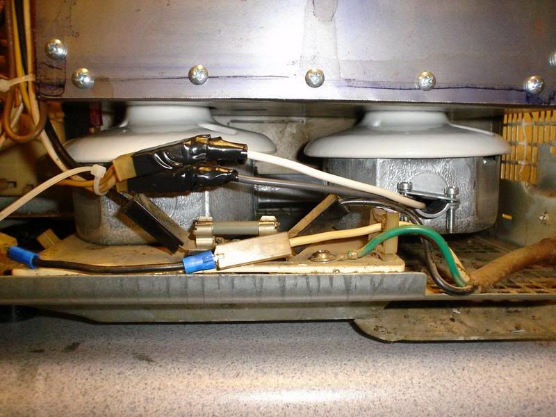
DISCHARGE THE HIGH VOLTAGE CAPACITOR! Do this by shorting across the terminals with an insulated screwdriver. The capacitor will generally be an oval can, approximately 1" x 3" and 4" or so tall. Failure to do this could result in a severe shock. The capacitor could still have many hundreds of volts of charge even if the machine has been unplugged for a significant period of time.
Tools required:
Phillips and flat screwdrivers
Pliers
Wire cutters/stripper
Hand brake AKA “hand seamer”
Assortment of hole saws
Hand drill and drill bits
Tin snips
Multimeter (as required to diagnose faults)
Thin Sharpie marker
Combination square
Ruler
Prussian blue
Sharp scriber and layout dye. (dye optional depending on preference)
Dead blow hammer or similar, plastic
3x 4" C-clamps or equivalent
3x 3/4" x 4" x 1' hardwood
Supplies required:
Two keyless PORCELAIN light fixtures suitable for at least 300W
Two octagon boxes
One 1/2" offset or straight EMT nipple
One NM connecter, or a rubber grommet to fit a 1/2" knockout
One Radio Shack 120V computer fan, Catalog # 273-242 or equivalent
#12 high temperature wire
Zip ties
#8 x 1/2" pan head sheet metal screws
#8 x 1 1/2" pan head sheet metal screws
Sheet metal, approx 3' x 3', 20 to 26 ga.
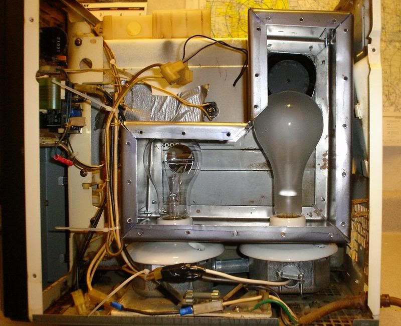
At least one 150W and one 300W light bulb
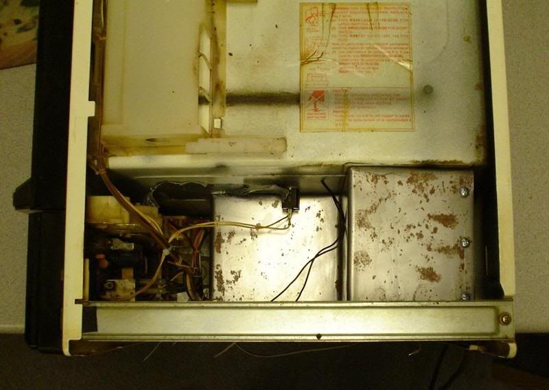
1) Now that you have a microwave in hand, let's start by removing the covers. Once inside, begin by discharging the high voltage capacitor (see above). Now locate the schematics and service information packet. These should be secured to a flat surface inside the cover or on the cooking cavity. You'll need these later.
2) Locate the high voltage power supply and magnetron. Begin by marking the input power wires to the high voltage power supply. These will become the switched lines for the light bulb heater. Disconnect and remove the power supply, HV capacitor, and magnetron. Also locate the magnetron and oven thermal cutouts. Bypass or remove these as required.
3) Locate the magnetron cooling fan. Mark the wires supplying power to the fan and disconnect them. Remove and discard the magnetron cooling fan.
4) If your microwave doesn't have a turntable it will have what is called a "stirring motor". This motor turns the waveguide assembly (microwave antenna) to ensure that the cooking cavity is evenly saturated. The stirring motor is not required for warmer service, so locate it's power supply wires and disconnect it. Terminate the wires in compression terminals to prevent shorting. You will likely be unable to remove the actual motor without significant disassembly of the microwave frame, this will not affect operation.
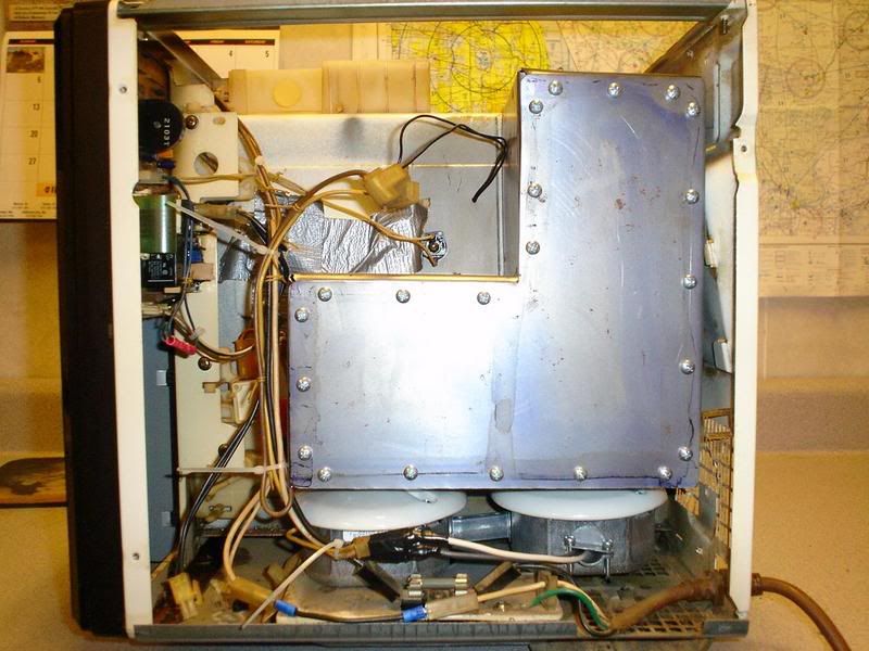
5) Now that you have the un-needed equipment removed, find a suitable location to mount two octagon boxes and two keyless light fixtures. The octagon boxes should be mounted side-by-side on a flat surface as close to the cooking cavity as the projection of the keyless fixture will allow. The two boxes should be connected together by the EMT nipple. Be sure there is sufficient room to mount the light box around the light bulbs. Experiment with different locations before screwing them down with several #8 sheet metal screws.
6) Now wire the fixtures. Wire them in parallel to ensure that both light bulbs receive full line voltage. Although the temperature inside the octagon box doesn’t seem to exceed 100F, I suggest you use a conductor rated for at least 300F. Your local electrical supply can help you with this. Be sure to make mechanically as well as electrically sound connections.
Now that you have the fixtures wired, connect the light bulb heaters to the power supply wires you disconnected earlier. Close the oven door, plug in the microwave, and test that your circuit works by installing both light bulbs and doing a time cook. You should hear the main power relay click and the light bulbs should light. If the main power relay clicks but the light bulbs do not light, check your wiring. If the main power relay doesn't click check the door interlocks per the service instructions.
7) Now that you have the light bulbs working it's time to bypass the interlocks. Most microwaves I've encountered have three interlocks. One signals the computer that the door has been opened canceling the cooking cycle, one directly disconnects the magnetron power supply from line voltage, and one switch shorts the input lines of the power supply. On my particular oven the only switch that you must circumvent is the primary interlock. This switch signals the computer that the oven door has been opened and the computer responds by ending the cooking cycle. Not very handy when you open and close the door to get clay! Defeat this switch by clipping the wires and splicing them together. I left the other two switches in operation. This shuts off the lights and stirring fan when I open the door, but because the computer does not cancel the program they come back on as soon as I close it again.
8) It's now time to interface the light box with the cooking chamber. Begin by installing your light bulbs again. Now trace a box onto the cooking cavity large enough to encompass them while leaving at least 1" of clearance in all directions. The box should extend approximately 1/4" below the neck of the bulb socket of the keyless fixtures to allow them to project into the light box. A small combination square will help to transfer these points to the cavity wall. Be sure to leave plenty of clearance above the bulbs for replacement!
9) Now that you have the outline of your box set up, trace another outline 1/2" inside it. This is the inner limit of the mounting flanges of the light box, cut two holes within these lines with a hole saw. One hole should be as close to the bottom and as far away from the fan location as possible. This will be the light box intake hole and should be roughly 1 1/2" in diameter
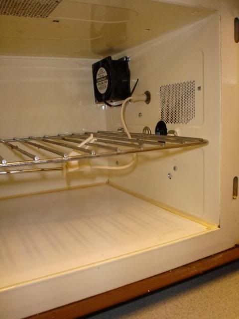
Now locate the fan you purchased and measure it to determine the hole size required. The Radio Shack Catalog# 273-242 requires a hole 3 1/2" in diameter. Cut this hole as close to the top as your inner lines will allow. Now mount the fan inside the cooking cavity to suck air from the light box into the cooking cavity. I suggest #8 x 1 1/2" sheet metal screws for mounting. Drill the fan mounting holes as required to fit the screws.
Connect the fan wires to the magnetron cooling fan power supply wires. This will switch the fan on and off with the light bulbs on a separate circuit. Plug the microwave back in and test to see that the fan and light bulbs operate.
10) All that's left now is to make the light box itself. To do this with a minimum of tools I suggest you obtain two strong and square pieces of hardwood approximately 3/4" by 4" by 1'. By securing the sheet metal between the wood and clamping everything to a workbench it's possible to bend the metal with reasonable accuracy.
Proceed as follows:
10a) Layout the main trace marks you made back in step 8 1:1 on a piece of paper. Measure the total exterior circumference and add 1". This is dimension A. Now measure the depth of the box, allowing for 1" or so of clearance around the lightbulb. This is dimension B. Now cut out a section of sheet metal dimension A long and dimension B +1" wide.
10b) Starting from a top corner, scribe off the center of every bend onto the sheet metal. Scribe lines 1/2" from both long edges and one short edge. These will show where to bend the tabs in.
10c) Drill a 1/8" hole at the apex of every bend. Then cut a 45 degree relief notch that intersects the hole. This is to allow relief for the mounting tabs.
10d) Begin bending up the box. This is a trial-and-error procedure based on the box design. I suggest you practice with scrap sheet metal first. Try to bend the mounting tabs in with a hand brake first. Then insert the section lengthwise in between your hardwood boards and clamp down. The scribe line should be approximately .050" from the edge of the board. Using your third board to distribute the blows from a dead blow hammer, begin making the bends. The scribe line should end up approximately 45 degrees though the bend. Adjust the setback (the distace from the board to the scribe line) as required to get the scribe line centered on subsequent bends.
10e) After completing the final bend cut off the excess metal. There will be some misalignment of the final panel and the tab due to the bend allowance, but calculating this is beyond the scope of this paper. Secure the final panel to it's tab with several short #8 sheet metal screws.
10f) Now that you have a box, let's mark the positions of the keyless fixtures. Begin by measuring the OD of the neck approximately 1/4" down from the top. Add 1/32 to this dimension and pick out a hole saw. Now take some Prussian Blue and apply it liberally to the top of the keyless fixture. Take your box, place it against the cooking cavity. Using the vertical lines you scribed on the cooking cavity as a guide, slide the box down until it touches the top of the fixtures. Push down hard!
Now remove the box and turn it upside-down. You should have two decent impressions of the top of the fixtures. Center the hole saw on these impressions and saw out the holes. Test fit and adjust with a file as required.
10g) Mount the light box with short #8 screws from the inside of the cooking chamber.. Make a cover from the layout you made back in step 10a and attach it. If everything fits you're ready for a test!
11) Install the light bulbs, plug in the temperature probe, set the computer to hold 140F and hit start. It should reach 140F in 5-7 minutes. If this works, you're good to go! Put the covers back on and post a photo!
If you have problems try troubleshoot them individually. Attempt to isolate a common fault. Be sure that the interlock switches aren't causing problems. If nothing works, check the fuse. Microwave fuses are special fast-acting types and are very sensitive to current fluctuations.
|
|
geep
New Member
Posts: 26
|
Post by geep on Nov 17, 2006 19:52:16 GMT -8
Hi Steve,
I would be happy to put together a few photographs and some basic instructions on the conversion process. Anybody with a decent supply of hand tools should be able to do the conversion for under $50 in less than 8 hours.
Temperature control is via varying the duty cycle of the lightbulbs. Simply enter the temperature you wish to hold, then hit start. When the oven warms to temperature the bulbs switch off. Once the temperature cools 2-4 degrees the bulbs turn back on again. It will hold +- 2 degrees in a range between 81F and 180F.
You're right on the bun warmers. I was ready to plunk down $500- $800 on a massive warmer until the microwave went south. I think it would have easily held 200lbs of clay. I'm not sure I could apply that much in a day. ;D
|
|
geep
New Member
Posts: 26
|
Post by geep on Nov 16, 2006 22:43:03 GMT -8
This spring, when I got started with industrial clay, I was planning to buy a used bun warmer from a commercial kitchen supply. At least until my old microwave died. The microwave, a massive GE unit popular in the mid '80's, had one nice feature: A temperature hold function for cooking turkeys and ham.
Microwaves vary the temperature of the food by adjusting the duty cycle of the magnetron, basically turning it on and off. This is perfect for a clay oven heated with lightbulbs.
What I did was remove the magnetron and associated cooling fan and heatsink. In its place I installed two ceramic keyless lampholders rated for 600 watts. Around this I bent up a sheetmetal box with a door to access the light bulbs inside. The other half of the box backs up to the cooking cavity. A few holes between the bottom and top of the box and a small 120 V fan serve to circulate air between the ample space of the cooking cavity and the lightbox. One 150W and one 300W lightbulb serve as the heat source.
The neat thing about this modification is that it's plug-and-play. Plug the lightbulbs in parallel to the magnetron relay and the fan to the magnetron cooling fan relay. A little sheetmetal bending and it's ready to go. Result: A clay warmer that will hold +- 2F in under a day! The best part is it was free!
I'll try to post some photos in the next day or two.
Specs:
Capacity: About 50 lbs.
Warmup time: 140F in under 5 minutes.
Cost: About $10 for lightbulbs and misc parts
|
|
geep
New Member
Posts: 26
|
Post by geep on Mar 1, 2007 23:08:31 GMT -8
OK Steve, sounds good. This thread will continue on the new board! John |
|